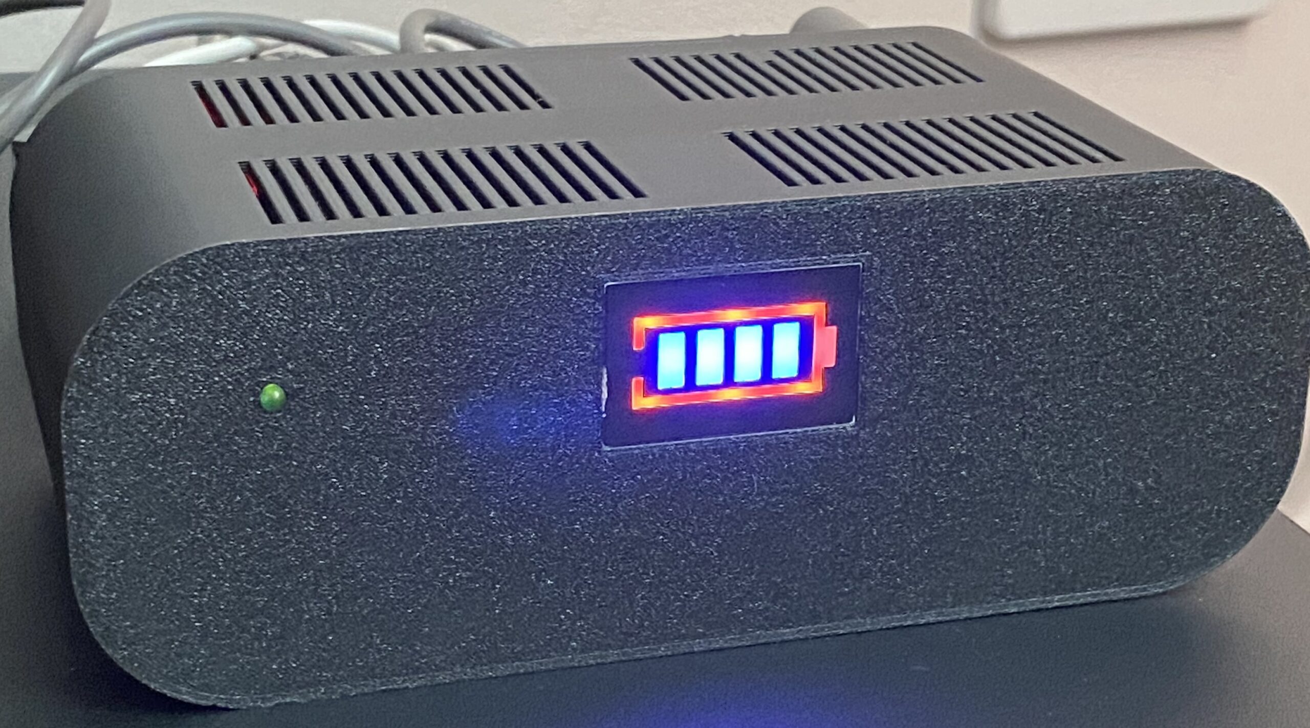
Recently our Dyson V8 cordless vacuum cleaner needed a replacement battery due to getting a frustratingly short run time with it. So I was left with a spare, but rather degraded, lithium battery pack. I didn’t want to get rid of something which I could potentially put to good use somewhere else, so I came up with a plan – a DIY Mini UPS!
The power to our house can be surprisingly unreliable given we live in the UK. Every time we have an outage the most annoying thing is that we have so many battery-powered devices (phones, tablets, laptops, etc) but no internet connection because the router has no power. Even for short interruptions, the router can take a few minutes to reboot, so I thought it would be pretty nice to have something to keep it powered for these occasions.
Whilst the house has multiple access points, switches and cabled connections, I decided that for these “emergency” situations, a single WiFi access point would suffice – keeping our laptops connected and able to work or play. To meet this minimum requirement, our router and ONT both require power.
My router is an aging ASUS RT-AC68U, which comes with a 19V 33W power supply. The Openreach ONT came with a 12V 6W power supply. The Dyson battery pack is a 6-cell li-ion battery, giving it a 22.2V nominal voltage, and is normally charged from a 26.1V 20.4W power supply.
This lead to my first concern – the total amount of power the supplies are rated for (33W+6W) is almost double what the Dyson power supply is capable of. If the router and ONT really do require that kind of power in steady-state then there is no way the UPS would work – there would not be enough power.
After a little testing with my ZigBee smart sockets, I was relieved to find they draw a fraction of that power, even when doing heavy workloads or rebooting. In fact, the power draw was so low I couldn’t really get a good reading – so well within power budget.
Circuit Design
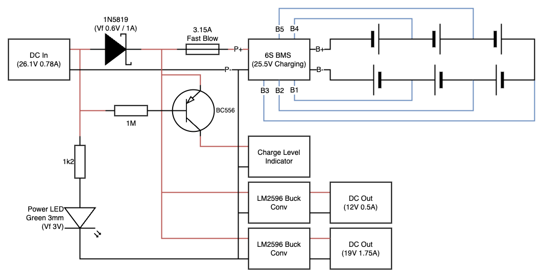
In a normal powered state, the DC In illuminates the green power LED and directly powers the two buck converters to supply our 12V and 19V outputs. It also provides power to the BMS board, which is responsible for correctly charging the 6-cell li-ion battery. In this condition, the PNP transistor will not conduct, keeping the charge level indicator off.
When the power fails, the battery starts to discharge via the power terminals on the BMS. The Schottky diode prevents current from flowing back to the green power LED, meaning it turns off. It also means the PNP transistor now will allow current to flow to the charge level indicator, powering it on. The buck converters continue to be powered, resulting in our outputs remaining on.
I added a fast blow fuse next to the battery to avoid any mishaps which might occur from a short circuit.
Components
Quite a few of the components were chosen because I already had them to hand. Equivalents would work just as well. I chose to standardise the jack sockets on the UPS to 5.5×2.5mm, then create custom cables for the ONT (which takes a 5.5×2.1mm jack) and the router (which takes a 4.0×1.35mm jack).
For the UPS:
- 1x 26.1V Dyson power supply – AliExpress
- 3x 5.5×2.5mm DC power jack sockets – AliExpress
- 1x 1N5819 Schottky diode – ebay
- 1x 1k2 resistor
- 1x 1M resistor
- 1x BC556 PNP transistor
- 1x 3.15A fast blow fuse
- 1x Fuse holder
- 1x 6S 25A balanced BMS board – AliExpress
- 1x Battery charge level indicator – AliExpress
- 2x LM2596 DC-DC buck converter boards – AliExpress
- 1x used Dyson V8 battery pack
For the cables:
- 2x 5.5×2.5mm DC power jack plugs – AliExpress
- 2x 1m 5.5×2.1mm DC powercable tail – AliExpress
- 1x 5.5×2.1mm to 4.0×1.35mm Right-angle adapter – ebay
Construction
First I took the Dyson battery apart to get to the cells. As an aside, the built-in BMS has a safety feature on it which took me a while to figure out. On the end of the BMS board is a reed switch which must be activated with a nearby magnet in order to activate the pack. I was replacing the BMS anyway, so this wasn’t a problem, but it did cause confusion as to why the battery wasn’t powering up!
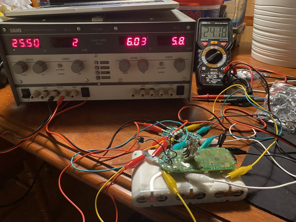
After testing that the BMS worked, and I could charge and discharge the battery pack, I was confident enough to solder all the components together to create the circuitry for the UPS.
The buck converters needed tuning to give an appropriate 12V and 19V output, but that was done pretty simply with a screwdriver. I measured the voltage with a small resistive load on each one to better simulate the real load it would be serving, rather than just an open circuit.
Satisfied with a working solution, I set about designing a suitable enclosure to finish it off properly. I use onshape for my CAD. My enclosure files can be found here.
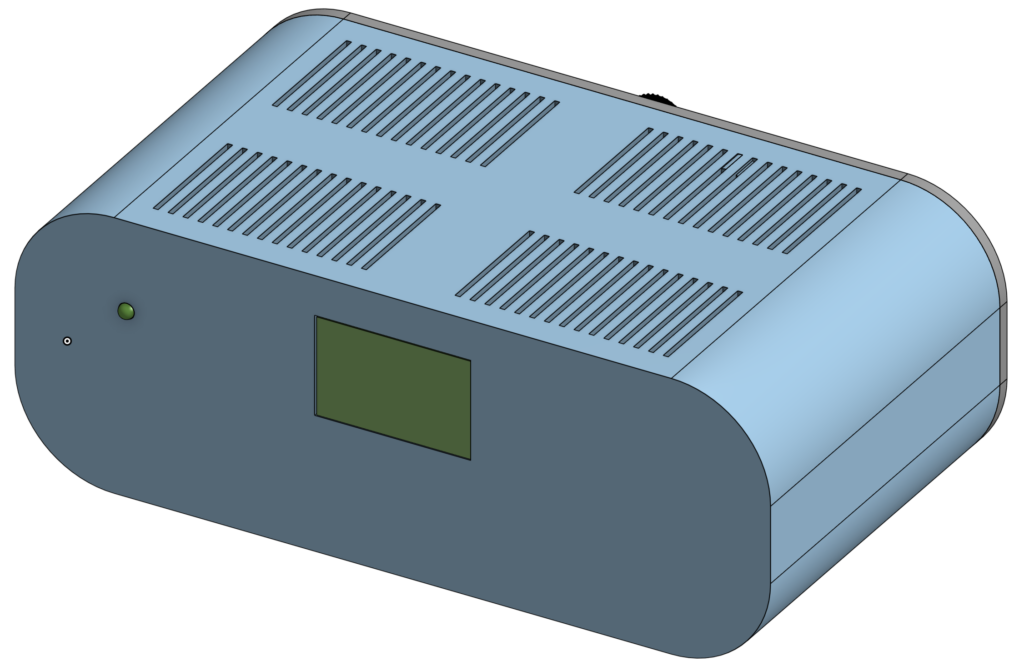
The enclosure is designed so the battery pack is secured at the bottom, then there is a sliding removable shelf where the BMS and buck converters are located. I used a spot of hot-glue to secure those in place. All the jacks and fuse holder are mounted on the rear, and the rear panel is secured to the rest via three M3 bolts.
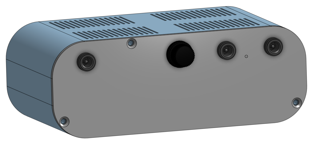
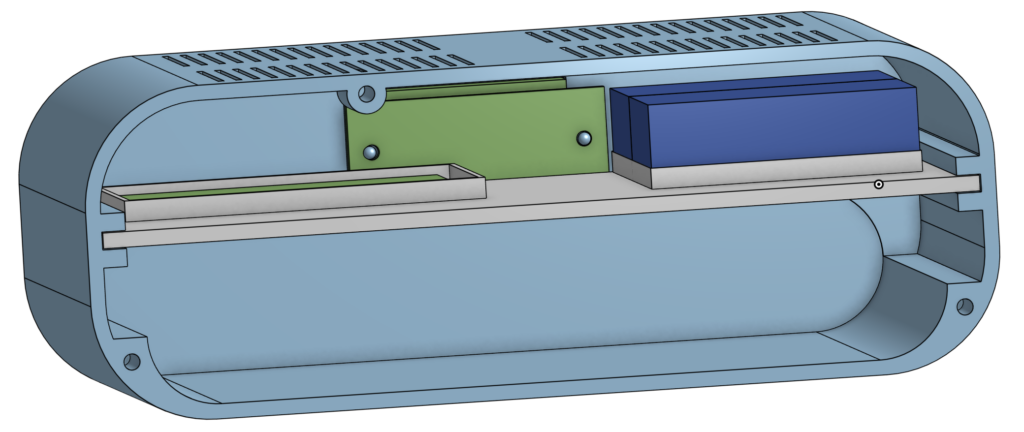
I printed the enclosure on my Bambu Lab P1S using black PLA+. Due to the extruded-style of the design, it printed very easily.
Wrapping up
The finished product!
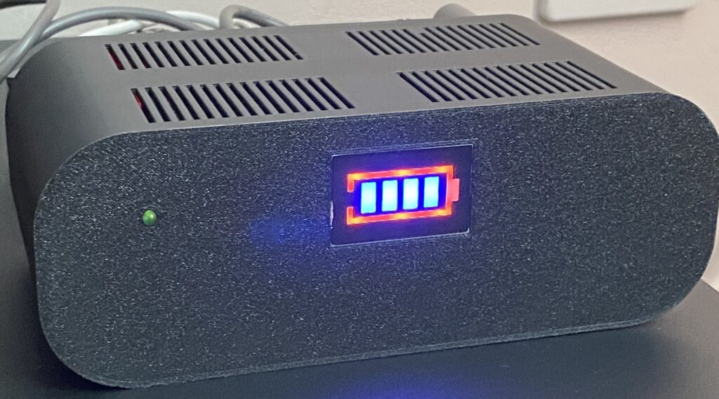
The real world testing I’ve done with my DIY Mini UPS shows it lasts 4 hours. For an otherwise “dead” battery, I’m really pleased with the results.
